Guitar pedals, the unsung heroes of countless iconic sounds, rely on precise voltage for optimal performance. A seemingly insignificant voltage fluctuation can drastically alter your tone, leading to frustration and subpar results. Understanding how to accurately measure the voltage your pedals receive is crucial for troubleshooting buzzing, signal drop-outs, or simply ensuring your effects sound their best. Incorrect readings can lead to unnecessary repairs or even damage to your expensive gear. Therefore, mastering the art of accurate voltage measurement is a vital skill for any serious guitarist or pedal enthusiast.
This article will guide you through a step-by-step process to confidently take accurate voltage readings from your guitar pedals, ensuring you always get the clearest, most reliable signal. We'll cover everything from choosing the right multimeter to understanding polarity and interpreting your readings, equipping you with the knowledge to diagnose and solve voltage-related issues with ease.
Preparation and Safety Guidelines
- Multimeter
- Alligator clip
- Always disconnect the power supply from the wall outlet before connecting or disconnecting any cables from your guitar pedal or power supply. Failure to do so could result in electric shock.
- Use a multimeter with appropriate voltage and current ranges for your pedal's expected voltage. Using an incorrectly configured meter can damage the meter or the pedal.
- Ensure the multimeter's leads are securely connected to the appropriate test points on the pedal. Loose connections can lead to inaccurate readings and potential damage.
Step-by-Step Instructions
Prepare for Measurement
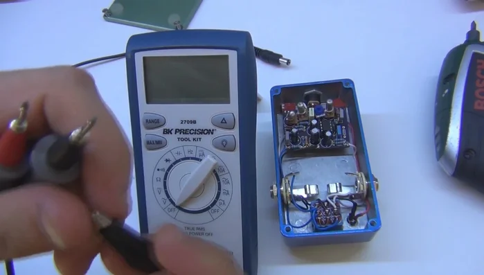
- Connect the multimeter's negative lead (using an alligator clip for ease) to the ground of your circuit. In guitar pedals, this is often the enclosure or, preferably, the shield of the input/output jack.
- Set your multimeter to DC voltage mode (the symbol with a solid line and dashes).
- Power the pedal.

Prepare for Measurement Measure IC Voltages
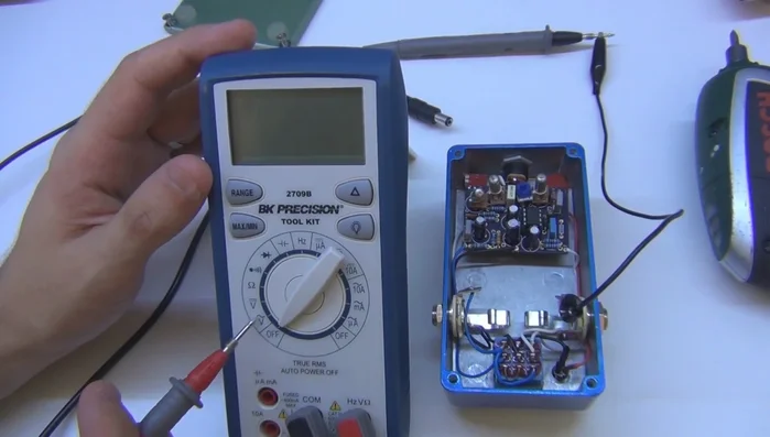
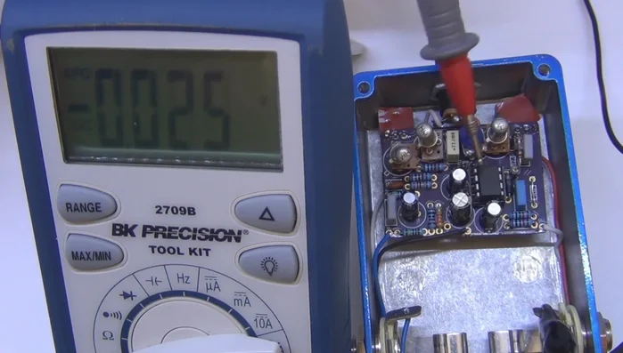
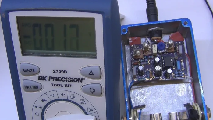
- Systematically measure the voltage at various points on the circuit board, focusing on the transistors and integrated circuits (ICs).
- When measuring IC pins, follow the numbering sequence (typically counter-clockwise starting from pin 1).
Measure IC Voltages Measure Transistor Voltages
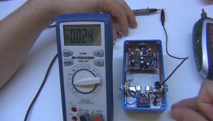
- For transistors (BJTs), identify the emitter, collector, and base pins using the transistor's datasheet. Measure the voltage at each pin.
Measure Transistor Voltages Record and Analyze
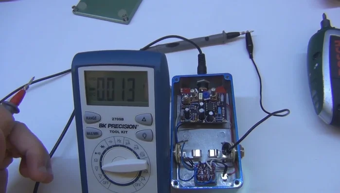
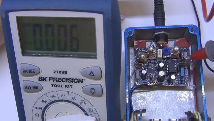
- Record all voltage readings accurately, noting the corresponding component and pin numbers.
Record and Analyze
Read more: Best Multi-Effects Pedals for Guitarists in 2017: A Comprehensive Review
Tips
- Connecting to the jack's shield provides a more reliable ground connection than the enclosure itself.
- Don't measure every component; focus on transistors and ICs for efficient troubleshooting.
- Refer to datasheets to identify transistor pinouts to ensure accurate measurements.
- If a transistor's emitter is connected to ground, the voltage reading will be zero.
- Compare your readings with expected voltages (based on the schematic) to identify potential problems.